
Sponsored Content
Background
In PV systems, ground faults are a relatively common type of fault, but the damage to the inverter equipment is also more serious. Therefore, it is necessary to eliminate the fault in time to restore the system to operational state. This Solis seminar will share with you the causes and troubleshooting methods of PV system ground faults.
Fault Description
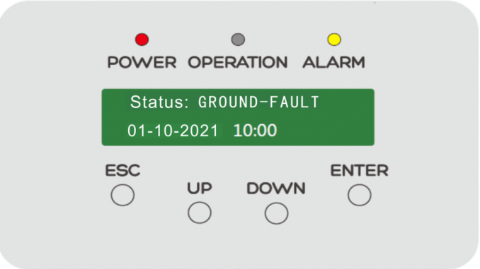
In a solar photovoltaic system, if a ground fault occurs, the inverter will display a “GROUND-FAULT” alarm when it starts running, and the alarm code is 1033H. At the same time, it will disconnect from the grid until the fault is eliminated.
Potential Cause of the Issue
- PV string grounding: There are generally three reasons for PV power station string grounding faults:
1) The insulation layer of the DC cable of a PV panel in the string is damaged and connected to the metal bracket.
2) The connection plug (MC4) of a PV panel in the string is poorly sealed, and it is connected to the metal bracket.
3) The insulation layer of the DC cable connecting the string to the inverter is damaged and connected to the ground.
Troubleshooting:
Disconnect the DC switch of each PV string connected to the inverter, and use a multi-meter to measure the voltage of the PV+ to ground and PV- to ground of each string. This will identify which string has the ground fault.
Under normal circumstances, the absolute value of the voltage to ground at the positive or negative terminals should be between 100 ~ 1000 V, and this voltage will gradually drop to within 20V during the measurement.

If the string voltage of the PV+/PV- terminal to ground is unbalanced, (for example the voltage value of one polarity to ground is 0 V or close to 0 V, and the other polarity to ground voltage value exceeds 600 V, and the value shows no change), it can be determined that the PV string has a ground fault.
Then you need to focus on troubleshooting the identified faulty PV string to determine the precise faulty node.
In addition, a meg-ohmmeter can be used to measure the insulation resistance of the PV+/PV- line ends of the module side to the ground in series. The value should be greater than 2MΩ.

- AC side, line grounding: Usually the impedance between the AC side neutral wire and the ground wire is too low.
Troubleshooting method: You can use a multi-meter to measure the impedance between the neutral wire and the ground wire. The normal value should be close to zero. Otherwise, there is a problem with the connection between the neutral wire and the ground, and you should check the AC cable.
Note: Pay attention to safety and standard operation during measurement taking and any fault finding. Further assistance is available by contacting your local Solis service team. www.solisinverters.com