DC cables are lifelines of the Solar Power Plant and interconnect modules to combiner boxes to inverters. These cables constitute only around 1-2% of total solar project cost but have a significant role and impact on the power output with poor design and/ or cable selection leading to material safety and performance issues.
DC cables are certainly different than the AC cables in construction and perform power evacuation with certain differences in their operation. Though significantly cheaper, Normal AC cables must not be used for DC PV power evacuation. Copper is the ideal material for string DC cables due to the metal’s high flexibility, superior current carrying capacity and better thermal performance. The DC cables should be made of flexible copper conductors. DC power does not demonstrate the skin effect like AC power and therefore any small change in the copper per unit length of the conductor leads to significant impact on the power evacuation capability of the cable.
Duty parameters for Solar DC Cables
DC cables have to endure harsh conditions in India as they have to withstand high temperatures, ultra violet (UV) radiation, atmospheric ozone and fire risk for a life expectancy of 25 years.
High temperature
Sustained exposure to high temperature causes thermal ageing of DC cables.
Arrhenius law –thermal ageing rate doubles for every 10˚C increase in temperature.
Operating temperature of DC cables is typically less than 90˚C.
Technical standards specify testing of cables at 120˚C and require the cables to sustain for 20,000 hours, equivalent to 160,000 hours at 90˚C s per Arrhenius law.
UV radiation
UV radiation in sunlight gets absorbed in the conductor leading to cable breakdown. DC cables are coated with polymer coating (polyethylene or polyolefin) mixed with about 2.5% finely dispersed carbon black to reflect UV radiation. Ideally the Red and Black color used for the identification of the Cables should be in strip form and the outer sheath of both the cables should be Black only.
Such cables have been used for over four decades in outdoor use in the communication sector in Europe.
Fire
DC cables are required to be flame retardant. Low smoke, halogen free insulation is preferred for DC cables. Halogen free compounds are filled with inorganic mineral flame retardant additives.
Ozone
Absorption of ozone results in degradation of DC cables. To ensue durability of DC cables over a period of 25 years, EN standards recommend that cables be tested with ozone concentration of 200-250 parts per million at 40˚C for 72 hours.
Water
Cross-linking of polymer coating material enhances the ability of the cable to withstand exposure to rains and waterlogging. Amongst the techniques available, electron-beam crosslinking is the most efficient and most widely used.
Shock related hazard in DC cable
Damaged cable sheath may lead to electric shock as the conductor would be exposed directly to the environment. Lighting circuit cable energized with an exposed end in the roof space may lead to an electric shock.
Due to above harsh operating conditions, the Solar DC cables are different in their operation to evacuate the power and therefore are subjected to changes in the operating parameters based on several operating parameters. It has been experienced in DC cable that issues like significantly lower yield of solar Power or as extreme as fires. Power output loss in DC cables should be 0.5-2%, however based on the design, copper content and manufacturing process deployed actual losses can be significantly higher. However, Lack of Module, SCB, ACB level monitoring makes it difficult to quantify /measure the actual losses in cables.
Manufacturing Process of DC cables Electron Beam Cross Linking
Under this process, the energy from the electrons creates active sites on the polymer chains which subsequently crosslinks and forms a chain making it hard for material to melt and flow.
Physical cross-linking
The cable insulations should be cross linked with high-energy electrons (betarays) in E-Beam irradiation facility. The electrons cede their kinetic energy when slowed down in the polymer. Through the impact of the electrons radicals are built, which with chemical reaction interlink the molecules.
Electron Beam Cross-linked insulating materials
Cross-linking binds together the polymer chains by means of a chemical linking (in the amorphous phase). This leads to a three-dimensional network. The polymer chain can no longer move freely (irrespective of temperature). Above the melting temperature the material can no longer flow but it goes into a rubber-like elastic state.
 Electron-beam cross-linking
Advantages of E Beam cross-linked insulation materials
■■ Increased shear and compressive strength
■■ Improved integrity in case of electrical failures (overload, short
circuit)
■■ Improved resistance to chemicals
■■ Infusible, soldering iron resistance
■■ Improved impact strength and crack resistance
■■ Better weather and abrasion thermalresistance
With the electron-beam accelerators the insulation materials can be cross-linked
within a few seconds. The homogenous irradiation and implicit the homogenous
cross-linking are ensured by thererfore especially adapted handling systems.
Other than in the chemical cross-linking in the irradiation cross-linking
no peroxides or hydro-silicones are incorpored into the synthetic mixtures.
Cable used in solar PV plants can be classified as follows:
DC cables
DC cables connect modules to inverters and are further segmented into two types:
String DC cables: These cables are used to interconnect solar modules and to connect modules with string combiner boxes or array combiner boxes. Cables for interconnecting modules come pre-connected with modules, whereas the cables required to interconnect strings and to connect with combiner boxes are procured separately. String DC cables carry current of only around 10 Ampere (A) and a small cross section (2.5 sq. mm to 10 sq. mm) is sufficient for this purpose.
Figure: Different types of cables in a solar PV project

Failures in DC Cables
There are many reasons why a cable may fail in service, with the failure at its most serious resulting in fire or other serious fault. Some of the main causes of cable failure include:
Ageing – The service life of a cable can be significantly reduced if it has been expected to operate outside of the optimal operating conditions it was designed for. The ageing process usually results in embrittlement, cracking and eventual failure of the insulating and sheathing materials, exposing the conductor and risking a potential short circuit, a likely cause of electrical fire.
Mechanical failure – If the cable is damaged either during installation or in subsequent use, the integrity of the cable will be affected and reduce its service life and suitability.
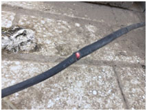
An example of mechanical failure in the solar DC cable
Shielding losses / EMC problems – Increased electromagnetic interference (EMI) occurs when the shield, which is designed to protect cable, signals from electromagnetic fields, breaks and abrasions due to continuous bending.
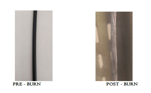
Case of burnt cable
Technical standards
Globally there are three recognized standards for use of DC cables – European (EN), Underwriters Laboratory (UL) of USA and TUV of Germany. The fourth standard, IEC, is currently a work in progress document.
UL standards
UL is an independent safety science company based in USA. It published the first edition of DC cable standards in 2005, which was named UL4703. Subsequently UL has amended the standards from time to time. UL standards are the most stringent for DC cables globally. UL standards require DC cables to be rated at 2,000 V, the highest among all standards. They allow use of halogenated compounds for making the cables flame retardant even at higher voltage.

Example of an accelerated thermal ageing Arrhenius- Diagram
3.2 EN standards
These standards published in 2014 and named EN50618, are relatively less rigorous than UL4703. The standards require cables to be able to operate at 1,500 V and specify that the DC cables must be low smoke, halogen free and must have cross linked insulation and sheath. Unlike UL standards, EN standards require cable to comply with Class 5 i.e. the cables must be flexible.Thus, aluminium by virtue of being a relatively rigid metal doesn’t qualify, effectively meaning that EN standards mandate use of copper cables only.
3.3 TUV standards
TUV2Pfg1169/08.2007 is relatively less stringent than the EN standards. A newer version, TUV 2Pfg1990/05.2012 was published in 2012, which requires cables to be rated at 1,500 V.
This standard requires the cables not only to be halogen free but also pass fire protection test as per the UL standard without any use of halogenated compound.
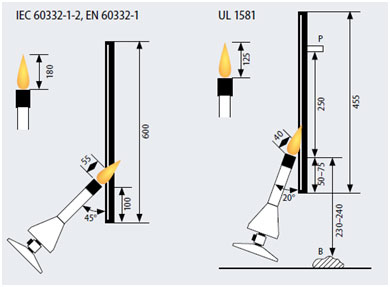
Test setup for Flame retardance test as per IEC and UL stnadards
3.4 IEC standards
The key difference is that IEC allows usage of class 2 material, i.e. aluminium for fixed installation. This implies that aluminium can be used for main DC cables, but not for string DC cables, as these cables requires flexibility.
IEC 62548:2016 sets out design requirements for photovoltaic (PV) arrays including DC array wiring, electrical protection devices, switching and earthing provisions.
The new standard includes a number of requirements for construction, materials and testing which cover these environmental threats, as well as covering the electrical requirements of operating to 1.5kV and at high current loads.
The IEC standard is similar in many respects to the European standard, it does however, permit non-halogen free materials to be used as well as halogen free, with the same environmental and electrical performance being achieved.

Standards used in India
BIS Standard
MNRE has indicated that, BIS shall soon adopt a standard for testing and certifying Solar DC Cables There are various Indian standards that are referred for testing of cables on various parameters. Indian Standards have also come up with laying parameters of halogen free compound, flame retardant properties of the cable, etc. Some of the popular/important standards are:
IS – 10810 – (various Parts)
IS – 8130
Public sector organizations such as National Thermal Power Corporation (NTPC) and Neyveli Lignite set detailed requirements for DC cables for their own projects, typically setting benchmark for the entire sector:
Voltage drop limit
Neyveli Lignite has mandated limiting aggregated voltage drop to 1%. NTPC has mandated limiting maximum voltage drop to 1% in string DC cables and 1.5% in main DC cables. These are very stringent standards as national electric code of USA limits the aggregate voltage drop to 5%9.
String DC cables standards
Neyveli Lignite has mandated compliance with TUV2Pfg1169/08.2007. NTPC used to follow TUV2Pfg1169/08.2007 or EN 50618, but has recently mandated only EN50618. This shift is primarily for want of higher thickness of insulation and sheath to cope with tougher operating conditions on site.
DC cable design and selection
Voltage drop typically leads to heating up of cables and increase in temperature associated with increased losses, higher voltage drops may lead to fire accidents. Power loss in DC cables is measured in terms of voltage drop from module to inverter. As current in the cables remains the same, voltage drop implies proportionate loss of power.
Limiting voltage drop
Use of larger cross section cables
Resistance of a conductor is inversely proportional to the cross section. Cables with larger conductor cross section cost more but offer lower resistance. For example, a 2.5 sq. mm cable has 60% higher resistance and a 6 sq. mm cable has 50% lower resistance vis-a-vis a 4 sq. mm cable.

Correlation of cable cross section and resistance for string
DC cables
Upsizing the cable from 4 to 6 or 6 to 10 sqmm might not be a wise choice, as for relatively miniscule advantage there is a significantly higher impact capital cost. While higher cross section can bring lower resistance, it may also mean very high unwanted factor of safety and extra cost for more amount of copper.
Cardinal rule is there may be attempts to optimize the capital costs in order to reduce capital risk exposure but nothing can replace a prudent cable design for performance, efficiency and longevity.
Short-term cost considerations might actually bring higher levellized cost of power or in some cases higher maintenance/ replacement costs considering life-time performance and safety aspects and highest possible returns from these investments.
Reducing cable length
Total resistance of a cable is directly proportional to the length of the cable. Reducing length through design optimization is key to limiting the voltage drop. But cable length is subject to plant layout and there are sometimes other site specific limitations also in limiting cable length.
In 2011-12, a typical solar project used around 15 km/MW of string DC cables and 3-4 km/MW of main DC cables. This has now reduced to between 7-11 km/MW of string DC cables and 1.5-2.5 km/MW of main DC cables effectively reducing voltage drop by around 33% in string DC cables and 30-60% in main DC cables.
A common solution for reducing overall DC cable length is the use of ‘Y Connectors’ to combine two strings and create a single output of double rating. This requires cable of larger cross section for carrying the larger capacity but halves the length used resulting in reduction on voltage drop offsetting a part of reduced losses in DC side.
However, increasing the number of crimp points or termination points leads to likely voltage drop. The design with usage of Y connectors should therefore seek an overall reduction in voltage drop. Another solution for reducing cable length is use of string inverters instead of central inverters. String inverters are used in place of combiner boxes and reduce the length of DC cables required. However, they require an increase in the length of LT cables potentially increasing the losses in the AC side.
Further, the total capital cost of project could increase as string inverters are expensive vis-a-vis central inverters.
Increasing operating voltage
Voltage drop in percentage terms can be reduced by increasing the operating voltage.
Average length of string and main DC cables used in a typical solar project in India has come down from 15 km/MW and 3-4 km/MW in 2011 to about 8 km/MW and 2 Km/MW respectively. With large scale projects shifting towards 1500V operating voltage for DC systems the cable requirement per MW will be further lowered.
Until 2016, the most prevalent DC operating voltage was 1000 V. But 1,500 V systems have become common now reducing losses by 40% in main DC cables.
The US market is already using 1,500 V systems, reducing voltage drop by a further third. The higher cost and poor availability of compatible modules and other BOS components is a challenge in the near future but Indian solar market has already moved to 1,500 V.
As DC cables operate at relatively low voltage levels resulting in high loss of energy, design optimization is crucial. Final design should aim for minimizing the cost of solar power generation without compromising on safety and quality.
Practical issues during plant operation
Actual voltage drop during operations could be significantly different from what has been calculated during design stages. Some of the practical issues in measuring and limiting voltage drop are given below:
Issues with voltage drop measurement
Measurement of actual voltage drop is very difficult. Theoretical voltage drop is calculated using cable specification sheets but actual ambient conditions including temperature, humidity and air quality are often vastly different. Voltage drop at inverter can be caused by lower power generation from modules and/or faulty interconnections. Significant effort is required to isolate and quantify the role of cables in voltage drop.
Use of poor quality copper
Use of high purity virgin copper is preferred for DC cables. However, inferior products are commonly supplied in the market. It is very difficult for developers and EPC players to ascertain purity levels.
Laying cables
It is common industry practice to lay DC cables via underground conduits to protect them from rodents and enhancing regular cleaning activities.
However, high temperature in underground conditions causes derating of cables
If the cables are left exposed in the air, 360˚ air flow around the cable helps in better heat dissipation.
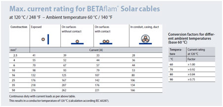
On the other hand, if cables are placed on surface or inside the conduit, air flow is restricted resulting in excessive heating of cables. This reduces the current carrying capacity of the cables.
Maximum current carrying capacity of DC cable
Inference
DC cables represent only 2% of overall capital cost of a solar project but suboptimal selection and/or design can lead to much greater opportunity loss over the years through loss of output, higher operating costs and risk of fire accidents etc.
ESTIMATED LOSSES FOR 1 MW CAPACITY SOLAR POWER SYSTEM
| Cable Losses | Optimal Units | Gain/Loss | Monetary Value in INR | Gain in INR |
| 2.0% | 14,32,690 | Decrease in 7,310 units. | 35,81,725/- |
(18,275) |
| 1.5% | 14,40,000 | – | 36,00,000/- | |
| 1.25% | 14,43,654 | increase in 3,654 units. | 36,09,137/- | INR 9,137 |
| 1.0% | 14,47,309 | Increase in 7,309 units. | 36,18,274/- | INR 18,274 |
| 0.75% | 14,50,964 | Increase in 10,964 units. | 36,27,411/- | INR 27,411 |
**Assumed value of 14,40,000 optimal units at a loss of 1.5%.
**Calculation has been done considering 14,40,000 units as reference.
- If the cable losses increase, the numer of units would be Less hence the monetary value will also decrease at the certain rate per unit. Here, the unit rate taken is about 5 INR /unit.
- Due care needs to be given to cable section, specifications and layout bearing in mind project specific factors including site layout, ambient conditions and other equipment selection. Key overall objective should be to minimize leveled cost of power rather than to reduce upfront capital cost of the project. This change in mind-set together with improved technical and operating awareness is critical to successful long-term operating performance and maximizing financial returns from the project. Very importantly, it is clear that DC cable design and performance related issues are still not fully understood. As India marches towards its ambitious goal of 100 GW by 2022 and spends billions setting up new solar capacity and the associated infrastructure, both the government and private sector should make more efforts to:
Setting up more technical training and quality testing infrastructure across India.
References:- 1. Bridge to India report on DC cables
2.LEONI Internal Knowledge bank
Indian Solar DC cable Market
India has added solar capacity of 5.5 GW in 2016-17, registering growth of 370% over last 3 years. New capacity addition Y-O-Y can be fairly estimated to be around 9(-/+1) GW in mid term. As the sector growth is heavily dominated by the govt. tenders on reverse auction basis, the whole value chain in under an increasing amount of pricing pressure.
The cut throat competition to keep self in the game, is leading to products designed for price. This also implies inherently inferior quality, safety and performance figures. A sizeable no of poorly performing projects have triggered several quality control measures by MNRE. It is certainly worthwhile to take note of the imminent losses to investors/ end users, as these measures may take time to trickle down to the projects under implementation.
The situation in relatively organized govt. tenders sector (ground mount and rooftop) can be extrapolated to the unorganized sectors like the Rooftop & distributed Solar, Solar home systems & Solar Pumps. While poor operating performance is a certain detrimental for new investors, it coupled with poor safety aspects and lesser longevity it is also expected to drive the end users away.
All of above is sure to bring concerns and doubts for the market and will be an impediment to evolution of the sector into a mature and sustainable market.